The Development of a Combination of an Electrothermal Accelerator and Compact Ion Propulsion System
- The Write Way SVA Literary Magazine
- Mar 30, 2023
- 12 min read
Lev Ermakov and Matthew Murphy
High School Juniors
March 2023
Introduction to the Workings of Ion Thrusters
Throughout the last ten years, ion thrusters have become the propulsion system of choice for spacecraft, providing several important advantages that other propulsion system lack such as chemical engines (a propulsion system that utilizes chemical reactions to create thrust and are relatively low-specific impulse). Ion thrusters are high-specific impulse, meaning that the thrust they produce is nearly commensurate to the amount of propellant being used. This makes them more fuel efficient compared to chemical thrusters. In fact, when analyzing the fuel efficiencies of these two propulsion systems, ion thrusters demonstrated efficiencies of up to 90% while chemical thrusters only reached efficiencies of 35%. Additionally, ion thrusters are capable of accelerating spacecraft to a top speed of 90,000 m/s, and should a spacecraft maintain this speed throughout the entirety of its journey, for example, to Mars, it would take a minimum 7 days to reach its location, compared to 40 days by the fastest recorded chemical rocket. Although, this fast of a journey is currently unheard of since it takes an extensive amount of time for the thruster to reach its maximum velocity. Another fundamental flaw of an ion propulsion system is that they require a substantial amount of electricity to produce even a Newton of thrust. However, there is hypothetically no upper limit to the thrust that can be produced from an ion thruster as long as the required energy can be reached (Dunbar, Ion Propulsion: Father, Faster, Cheaper).
Ion thrusters generate a thrust by ejecting positively charged ions, formed through electron bombardment, at extremely high velocities. Primarily, to better understand how thrust is produced it is important to note that half of the ion thruster is a conical chamber (considered the upstream end) that opens up into the other half which is a cylinder (considered the downstream end). The shape of an ion thruster is essential to its mechanism of function. An inert gas is initially injected into the cylindrical, downstream chamber and travels toward the conical end. An inert gas is specifically chosen to ensure that unwanted and/or uncontrollable reactions do not occur. The conical downstream chamber ensures that the gas remains within the system long enough to ionize a majority of the atoms, as the ionization is not an instantaneous process. Simultaneous with the gas entering the chamber, electrons are produced from a hollow cathode, called the discharge cathode, located at the back of the thruster. Hollow cathodes are negatively charged electrodes that are composed of a hollow refractory tube (a tube that is resistant to high temperatures), an orifice plate (a circular disk that has an opening in the middle of it that is used to restrict the flow of a fluid or gas in a tube. The orifice plate is often comprised of stainless steel), and an insert. There are two main inserts: a coated tantalum foil or impregnated porous tungsten. The insert can also be made of other various materials as long as it provides a low function surface on the inside of the tube. The insert is what is going to be the active electron emitter). The cathode is to be wrapped with a heater or an alternate heat-generating substance (e.g. a co-axial sheathed heater) which will heat the insert to emissive temperatures producing electrons that ionize a propellant that is being flowed through the tube. This forms a plasma from which the discharge-current electrons are extracted via the orifice plate and shot out into the ionization chamber (Chapter 6 cathodes 022208 - NASA). These electrons then hit propellant atoms and the resulting collision knocks lose one of the propellant’s free electrons producing 2 electrons and a cation.
Subsequently, the electrons are pulled towards the chamber wall via large magnetic fields being generated by permanent magnets, usually sintered neodymium magnets (Nd2Fe14B) are used since they are the strongest commercial magnet available. A permanent magnet is a magnet that retains its magnetic properties even in the absence of an inducing field or current. Magnetic fields are vector fields, meaning that they are fields of space in which every single point in that space is assigned a quantity of magnitude and direction. In order to establish a permanent magnet, also called a ferromagnet since it follows the description of ferromagnetism which is the strongest type of magnetism out of the four types, a substance’s electrons need to possess a preferred orientation and contain one or more unpaired electrons. Paired electrons have opposing spin values, which cause their magnetic fields to cancel each other out. Following the Pauli Exclusion Principle, (electrons first fill a shell, minimizing the amount of paired electrons) the more unpaired electrons, the more magnetic that substance/element will become (University of Illinois Urbana-Champaign - Four Different Kinds of Magnetism). Magnetic fields exert a force on any other charges or particles present in the fields changing their orientation or direction of travel. When a particle or charge is moving parallel to the field, there is a net magnetic force of zero. When a charge is moving perpendicular to the magnetic field, then the particle experiences a maximal magnetic force with the magnitude Fmax=qv ✕B (q is the quantity of charge, v is the velocity of the moving charge, and B is the magnetic field magnitude). As the velocity of the charged particle increases, so does the magnetic force applied to the particle; the same is true for the magnitude of both the charge and the magnetic field. It is crucial to note that a magnetic field does not change the velocity of the charged particle when traveling perpendicular to the magnetic field. Furthermore, if the magnetic field is uniform, then the trajectory of a particle moving perpendicular to the field will be circular. In order to find the magnitude of the magnetic force of a charge moving at the angle θ to a magnetic field, we use the equation F = qvB sinθ which is also the equation depicting cyclotron radiation/electromagnetic scattering as seen in Figure 1(Beatriz, Chapter 27 - Magnetic Fields and Magnetic Forces).
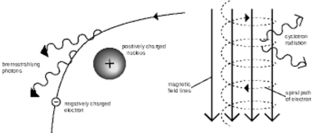
(Figure 1- Cyclotron Radiation)
It is also important to note that permanent magnets have Curie points which are specific temperatures dependent on the type of magnet, and once the magnets exceed that temperature, they become paramagnets meaning that they require a magnetic field to show magnetic properties and have much weaker magnetic forces. Because ion thrusters are generally used in space, where temperatures are extremely low, there is not a significant concern for the overheating of the magnets. Neodymium magnets additionally possess a Curie point of around 400°C meaning they will have resistance to the heat of the plasma, allowing for testing on Earth. The time electrons spend in the ionization chamber is maximized by their attraction to the magnetic wall. The electrons spend a longer time in the thruster as they are pulled towards the strongest point of the magnetic field. Since the time the electron and the propellant spend in the chamber is maximized, the probability of the propellant being ionized increases overall because the chances the electrons interacting with the gas atoms increases with the more time both particles spend in close proximity to each other, increasing the ionization efficiency of the thruster.
With the separation of the electron and positively charged ions, the final step in the process of generating thrust commences, involving the acceleration of the cations out of the thruster nozzle. To do this, we take advantage of the electrostatic force (the force of attraction or repulsion between charged particles). This force encompasses the idea that like charges repel, and opposite charges attract (Lim - What is an electric field?). Electrodes would be generating electric fields which are regions of space around an electrically charged particle or object in which an electric charge would feel force. The electrode closer to the inside of the thruster will be a highly negatively charged cathode (accelerator grid) while the electrode closer to the outside will be a highly positively charged anode (screen grid), as shown in Figure 2.
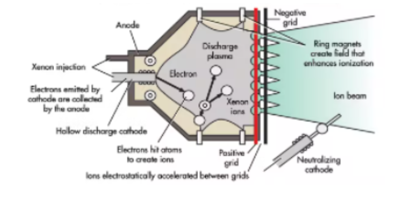
(Figure 2 - Electron Grid Diagram)
The greater the voltage difference between these two electrodes is, the faster the ions are accelerated. Each of these electrode sets, called grids, have thousands of minuscule holes called coaxial apertures that line up perfectly with each other and are evenly spaced out; these apertures electrically focus the ions. The ions are first accelerated towards the accelerator grid due to the forces of attraction where they are focused through the apertures of the accelerator and then repulsed through the apertures of the screen grid resulting in many ion jets and when all these jets are combined, the result is an ion beam. This ion beam illustrates the expulsion of cations at high speeds which results in the production of thrust. Refer to Figure 3 for detail on how all parts fit together. The only limitation of the amount of thrust an ion thrust can produce is the voltage applied to the grids which is an indefinite amount. Additionally, cations are utilized to generate thrust rather than electrons because of their greater mass meaning that the thrust produced will be greater as determined by the rocket thrust equation F = ṁ Ve + (pe - p0) Ae which indicates that as the mass flow increases so does thrust produced. Over time, the ion beam’s cations begin to circle back, feeling an increasing attraction to the growing negative charge of the thruster as a consequence of the production of all the electrons. To counteract this, an additional hollow cathode is fixed at the top of the thruster, facing towards the ion beam that would produce electrons to neutralize the charge created from the expelled cations (Webber, 2011).
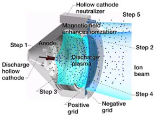
(Figure 3 - Ion Propulsion System Layout)
Engineering Goal, Design, and Construction
When developing an aeronautical craft to be launched into outer space, the size of the craft is a constraint, influencing its size and shape, therefore, indirectly limiting its abilities since measuring instruments and other mechanisms generally increase the size of the craft. These are issues since there is limited cargo space in the rocket that would transport these aeronautical technologies to their desired locations in space. Possible solutions to this dilemma include: utilizing larger rockets, designing the craft so that it could contract into a smaller area and later expand in outer space, or minimizing the size of the components being used on the craft. The first solution presents the issue of cost since it would take more fuel to lift the rocket in addition to the issue of designing a rocket that is capable of holding and lifting the spacecraft. Furthermore, the second solution increases the time necessary to finish constructing the technology since there would be a need for moving parts that increase the potential for the technology to malfunction or break. While the third solution also increases the time necessary because of the development of smaller parts, future craft that need the same components would be developed at a more efficient rate and could include more mechanical components, resulting in larger craft, or in smaller rockets. One key part of spacecraft that intend to travel substantial distances would be ion thrusters and this year we were determined to figure out how to construct a compact ion thruster that is still capable of generating noticeable thrust.
Subsequently, we researched the workings of an ion thruster seeking a mechanism that could be replaced with a more efficient process or condensed. We discovered that the process of electron bombardment has a sole purpose of creating a plasma involving a discharge cathode and neutral gas that generally tends to be relatively expensive since Xenon is usually preferred. Seeking a mechanism to effectively replace electron bombardment we were introduced to electrothermal acceleration. Electrothermal accelerators are typically composed of a source of propane, a piezoelectrically-triggered torch head that would ignite the gas, and tubing that leads into a chamber with a miniscule outlet through which the gas, which is a plasma at this point, escapes. These accelerators generate plasma through means of burning the propane gas. Instead of releasing the superheated products into the air, the tubing forces the excited gas to stay in its plasma state of matter, while cooling as the combustion reaction halts, which results in the supercooled plasma of that reaction moving rapidly through the tubing, being pushed out by pressure, due to its thermodynamic properties. Electrothermal accelerators additionally do not necessarily require an expensive propellant, reducing the overall cost of the thruster. The accelerator that the electrothermal ion thruster will be utilizing would have propane as its propellant and a piezoelectric torch head that burns the gas at 3100°F. After determining that an electrothermal accelerator will be able to effectively replace the discharge cathode and all other mechanisms associated with the insertion of the neutral gas including the gas itself, we focused on designing a thruster conceptually similar to a typical ion thruster however, our thruster will be adapted to incorporate an electrothermal accelerator in place of all components needed for electron bombardment. This thruster should ideally fit within a 1 foot area.
To gain inspiration for our design, we decided to search for various other models of ion thrusters and encountered the engine developed by Alexander Reifsnyder. Alexander Reifsnyder designed a variation of traditional ion thrusters, modulated to ionize oxygen molecules in the air rather than excited plasma, with the whole model fitting in a one cubic foot area. This model was indeed compact like we intended to achieve with our own thruster yet his model had the major drawback of barely producing any observable thrust. However, his model was a cheap, working ion thruster that could be tested in a classroom with relative safety. Additionally, his model utilized copper couplings and nails as the electrodes which prompted the question of whether it is possible for us to utilize copper couplings as our electrodes.This information required verification and we decided to construct his model and collect our own data.
Reifsnyder’s model consisted of a 1 inch thick, 4.5 by 9 inch wooden baseboard with another identical wooden board positioned vertically and connected to the base board 3 inches away from one of the ends on the 4.5 inch long side. This vertical board has a total of seven 3-inch copper nails facing towards the other end of the baseboard and arranged in a honeycomb pattern with the center nail 4 inches away from the top of the board. These nails are each spaced out an inch apart and their heads are fully inserted pressing down on a strand of copper wire that wraps around each nail before sticking out to the side. One inch away from the nail tips are 7 copper couplings each about 1-inch in diameter, configured in the same honeycomb pattern and soldered together, being supported on a wooden peg that is 1inch thick, 3 inches tall, and 1 inch wide. Additionally, there is a copper wire that sticks out the couplings and when both wires that stick out are connected to an electrical transformer of at least 10,000 volts, thrust should be produced.
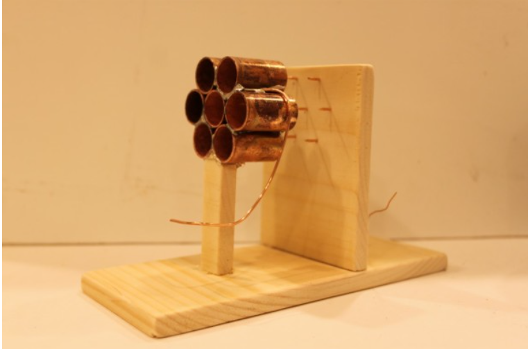
(Figure 4 - Prototype of Thruster)
In order to test the amount of thrust produced, one layer of a tissue, since this is what Reifsnyder used to test, is secured to beaker stand and position with the tissue 1.27 centimeters away from the nozzle of the thruster. It was found that at 1.27 centimeters, the tissue (which weighed 0.3 grams) was displaced an average of 1.27 centimeters and once the tissue exceeded this distance away from the thruster, no observable movement was observed. However, thrust was successfully produced meaning that the use of copper couplings as an electrode set, proved to work.
The gathering of the dimensions of components in the prototype allowed the creation of the initial schematic of the electrothermal ion thruster. The figures shown below describe the dimensions and configuration of the electrothermal ion thruster in addition to how the electrothermal thermal accelerator will be integrated into the final product.

(Figure 5 - Our Model Schematics)
Testing/ Data Gathering
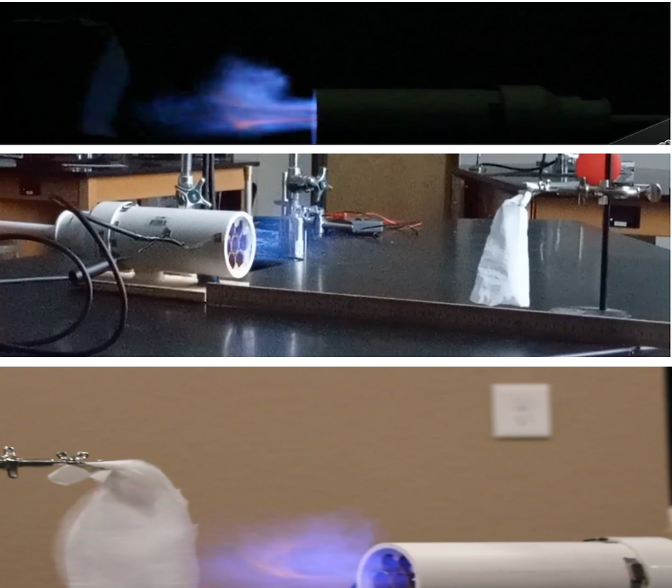
In addition to having certain systems such as the grids and discharge cathode be replaced with other components that still simulate the purpose of those original parts. The grids will be replaced with copper bearings with the intention of generating more electrostatic force which will accelerate the ions even faster and the process of electron bombardment would be replaced with an electrothermal accelerator that inserts tightly into the reduction coupling. The thruster is then set up with the beaker stand holding a 0.3 gram tissue (to keep consistent with the testing of the prototype allowing for an reliable comparison), a 1.3 gram balloon, and a 2.3 gram. These stands are placed 25 centimeters away from the thruster. After the electrothermal accelerator is primed, the electricity is released into the electrodes. Each configuration was tested a total of 20 times and the data gathered is as follows. Also, because an electrothermal accelerator does produce its own thrust, it was necessary to find proof that the ion thruster was producing its own thrust. After examination, it was noticed that the copper couplings had undergone a process of anodization that revealed that there was indeed a flow of charged particles past the couplings. This reveals how the ion thruster did create charged particles that did flow out the thruster providing evidence to support the idea that the thruster was correctly functioning.
Object with mass of 0.3 gramsx̄ = Δ 15.2 cmObject with mass of 1.3 gramsx̄ = Δ 9.8 cmObject with mass of 2.3 gramsx̄ = Δ 7.3 cm
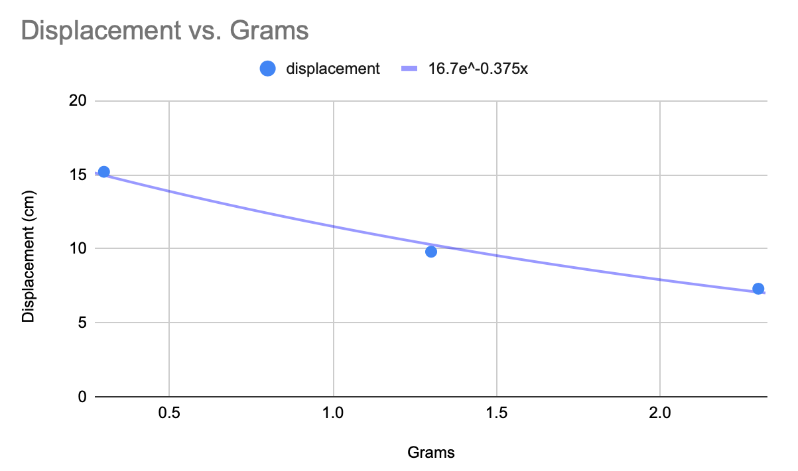
(Figure 6 - Mass/Displacement Trend)
Data represented by line of best fit: f(x) = 16.7e-0.375x
Conclusion/ Future Development
The testing revealed that the electrothermal ion thruster produced enough thrust to move the 0.3 gram object 11.97 times farther than Reifsnyder’s prototype meaning there was a 1097% increase in displacement. Additionally, Figure 6 illustrates the trend exhibited between the mass and displacement of the thruster. Overall, the Electrothermal Ion Thruster accomplishes our engineering goal since it produced observable thrust and did indeed fit within a 1 cubic foot area. With this data, it can be concluded that ion thrusters can be condensed and modified in various ways and still can generate thrust via the expulsion of ions. With further testing and development, this thruster may be able to generate thrust continuously and be utilized by actual spacecraft allowing for potentially smaller rockets or larger craft. These advancements could reduce the cost of space travel allowing for more budget to be put towards the actual development of new technologies.
Images

References
Four Different Kinds of Magnetism. 22 Nov. 2021, http://web.hep.uiuc.edu/home/serrede/P435/Lecture_Notes/Magnetism.pdf. Accessed 22 Nov. 2021.
Lim, Alane. “What Is an Electric Field?” ThoughtCo, ThoughtCo, 29 Aug. 2019, https://www.thoughtco.com/electric-field-4174366.
Beatriz. (2021, November). Chapter 27- Magnetic Fields and Magnetic Forces. Retrieved November 7, 2021, from https://physics.ucf.edu/~roldan/classes/Chap27_PHY2049.pdf.
Dunbar, B. (2004, November 12). Ion Propulsion: Farther, faster, cheaper. NASA. Retrieved November 8, 2021, from https://www.nasa.gov/centers/glenn/technology/Ion_Propulsion1.html#:~:text=Each%20set%20of%20apertures%20%28opposite%20holes%29%20acts%20like,%28called%20the%20accelerator%20grid%29%20is%20charged%20highly%20negative.
Jet Propulsion Laboratories. (n.d.). Chapter 6 cathodes 022208 - NASA. Hollow Cathodes. Retrieved November 7, 2021, from https://descanso.jpl.nasa.gov/SciTechBook/series1/Goebel_06_Chap6_cathodes.pdf.
Webber, C. R. (2011). Plasma, Ion Thrusters, and VASIMR. Boulder; University of Colorado-Boulder.
Comments